NOTE About this page
Equilibar valves are used today to solve many complex flow control applications. This page shows the early learnings of applying an Equilibar valve to control flow and is retained for historical archive purposes.
For the latest information about Equilibar flow control valves
visit our updated flow control page.
Traditional flow control schemes use variable orifice valves in conjunction with flow transmitters and a closed-loop PID controller. Alternatively, an Equilibar dome-loaded back pressure regulator (BPR) can be used in flow control schemes.
Simple PID Control Loop
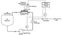
In the simplest flow control scheme, the Equilibar dome-loaded BPR uses an electronic controller and a flow meter in a PID control loop (see schematic at below). The electro-pneumatic pilot pressure controller translates the electronic signal from the PID into a pressure signal for the pilot pressure on the dome of the BPR. The dome-loaded regulator controls the flow by modulating the pressure at its inlet. Flow is decreased by raising the pilot pressure and increased by lowering the pilot pressure.
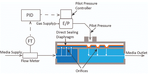
schematic of Equilibar back pressure regulator set up for flow control
Equilibar multi-orifice dome-loaded back pressure regulators are well-suited for this application. They offer several advantages over traditional flow control schemes in complex applications. Read more specifics about How Equilibar back pressure regulators are used for flow control, or watch the video below of how it works.

Equilibar is featured in the March 2019 issue of Flow Control Magazine. Read the article about using dome-loaded back pressure regulators to control flow.
Controlling Pressure Drop Across an Orifice
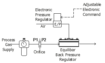
In an alternative method, a dome-loaded back pressure regulator can also be used to control flow by controlling the pressure drop across an orifice or an adjustable metering valve.
The schematic at right shows an open loop flow control scheme of this type. This works for controlling the flow of liquids and gases. The upstream pressure reducing regulator (PRR) sets the P1 pressure to the orifice. The back pressure regulator sets the P2 pressure to the orifice. By adjusting P2 with the back pressure regulator the differential pressure is controlled. If the orifice is of a known Cv or has had its flow characterized, the differential pressure across the orifice effectively controls the flow rate.
Open loop flow control using an orifice is demonstrated in the video below.
Controlling Pressure Drop Across an Orifice in Open Loop Control
Option for simple control without a flow meter: In some applications, the purchase of a flow meter may not be economical or practical, such as with severe service conditions. By maintaining the pressure upstream and downstream of an orifice, simple control can be achieved without a flow meter. The flow rate of most turbulent fluid systems is highly proportional to the flow rate, raised to the second power. (See orifice calculator)
Improved Valve Turn-Down Ratio
By replacing the fixed orifice in the previous schematic with a modulating variable orifice valve, a much wider range of flow rates may be achieved. Traditionally flow control valves may have a turn down ratio of only 10:1. Turn down is the ratio between the highest flow that can be controlled and the lowest flow that can be controlled. A 10:1 turn down means that is 10scfm is the highest flow when the control valve is wide open then 1 scfm is the lowest flow the control valve will likely be able to set with reasonable accuracy.
Traditionally if a higher turn down ratio was required, say 15:1, a second smaller flow control valve would need to be mounted in parallel. This is quite costly and requires a sophisticated control to allow the two valves to smoothly transition. An alternative approach is to retain the original larger 10:1 flow control valve. When low flow rates are required the differential pressure may be reduced allowing the flow control valve to produce lower flow rates.
Contact Us For More Information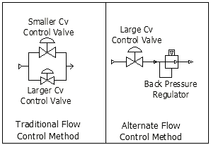
Closed Loop Flow Control
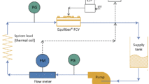
In the schematic below, a pressure reducing regulator is used to provide a stable gas pressure to a metering valve. The Equilibar back pressure regulator has its setpoint adjusted by an electronic pressure regulator (EPR) to control the downstream pressure on the Metering Valve. The flow transmitter is monitored by the PID controller to keep the process at the desired flow set-point. One real advantage of this is the reduced workload on the PID circuit and the increased speed of response in the system. Changes in the downstream system pressure are immediately and automatically compensated for when the back pressure regulator modulates to keep its input pressure (P2) at setpoint.
Request a Quote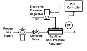
Flow Control using Closed Loop Control Scheme
Flow Control Against Pump/Compressor Flow Curve
In the schematic at right, the process works in the same manner. However, a pump or compressor can be used to supply a consistent pressure on the upstream of the Metering Valve. This schematic is valid for both process gases and liquids.
Interestingly, it is not necessary that the pump or compressor provide a constant pressure; as the flow rate varies, it is normal for the pump or compressor output pressure to vary. So long as the pressure at any given flow rate is relatively stable, the PID controller is able to provide good control. In fact, for some pumps or compressors, the Metering Valve could be eliminated altogether, with providing flow control by simply adjusting the point on the “pump curve” that the process is operating.
Contact Us for More Information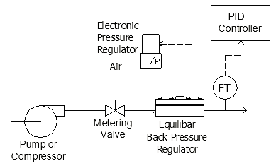
Flow Control With a Pump or Compressor
Why use an Equilibar Back Pressure Regulator for Flow Control?
- Wide Flow Range: Traditional flow control valves (FCVs) have an operating range from 10:1 to 15:1, whereas an Equilibar back pressure regulator (BPR) can easily be configured to control flow rate across a very wide flow range.
- Isolation from Downstream Pressure Changes: A BPR provides a buffer against changes in downstream pressure because it will automatically adjust to keep its inlet pressure at setpoint regardless of changes in its outlet pressure. When using a traditional FCVs, changes in downstream pressure or restriction will require a PID control adjustment.
- High resolution: Equilibar dome-loaded BPRs have ultra high resolution, zero hysteresis, and zero dead-band whereas traditional control valves have a deadband, providing less accurate precision. See details for high resolution flow control applications such as temperature control.
- Demanding service conditions: Equilibar BPRs are easily configurable for severe and demanding service conditions, sanitary applications, and continuous flow reactions.