While MFCs are a great solution for laboratory flow control and have accuracy as high as 0.5% of reading, there are a few operational limitations that can frustrate the research chemist:
- Most mass flow controllers have internal control valves that only operate with a limited differential pressure. This can be problematic for metering gases into high pressure applications, such as research reactors.
- The solenoid actuated control valves in the MFCs have orifices that are carefully selected for the intended differential pressure. Large changes in differential pressure cause tuning and range problems for these valves.
- Fluctuations in downstream pressure can disrupt the stability of the MFC flow rate as the PID controller has to adjust to changing pressure differentials.
Back pressure regulators are frequently located downstream of MFCs in research applications to overcome each of these limitations.
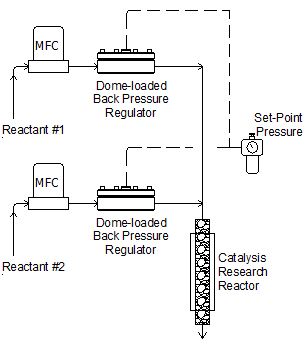
Equilibar Research Series back pressure regulators are available in stock for pressures up to 300 bar
Overcoming Limited Pressure Differential
For low pressure gas dispensing, the integrated control valve works quite well. However, for metering gases into higher pressure applications, such as research reactors, the control valve’s internal mechanisms often use springs that limit the maximum differential across the valve.
For example, to dispense N2 into a catalyst research reactor at 1200 psig, it might be desirable to supply the MFC with gas from a cylinder regulator set at 1400 psig. If the MFC valve had a maximum differential pressure limitation of 250 psig, this would work well for operating the reactor at its maximum steady state pressure (1200 psig). However, many research reactors are required to change pressure during the test cycle or they may require the dispensed gas to generate the initial reactor pressurization. In this case, it might not be possible to initiate flow with some MFCs when the reactor pressure is below 1100 psig.
MFC manufacturers sometimes recommend bypass valves to overcome this differential pressure limitation during start-up. However, if an application requires steady state operation through a wide pressure range, the bypass valve won’t address this problem.
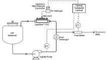
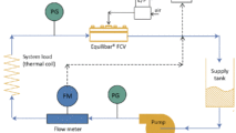
By installing a precision back pressure regulator, such Equilibar, downstream of the MFC, it is possible to maintain a fixed differential across the MFC valve at all times, regardless of reactor condition. In the above example, a fixed BPR pressure of 1300 psig would keep the MFC working stably regardless of the pressure in the reactor downstream.
Overcoming Tuning and Calibration Problems
The control valve orifice determines the Flow Coefficient for the MFC and is carefully selected by the factory based on the min/max flow rate combined with the min/max Inlet Pressure and the min/max Outlet Pressure specified by the customer at the time of purchase. The Flow Coefficient (i.e. orifice size) is determined by the square root of the pressure differential across the valve. If the customer needs to operate the outlet pressure at a significantly higher pressure than designed, both tuning problems and flow range problems can be encountered.
The installation of a precision back pressure regulator can be installed downstream of the MFC to simplify the valve’s tuning and range, as shown in the following examples:
- Maximum MFC differential specified by factory tuning: 250 psig (17 bar)
- Maximum reactor pressure: 1200 psig (83 bar)
- Minimum reactor pressure: 400 psig (28 bar)
- Set upstream supply pressure at 1400 psig (97 bar)
- Solution: Install back pressure regulator downstream of MFC at 1250 psig (86 bar)
MFC Instability with Downstream Pressure Fluctuations
Mass flow controllers utilize a PID (Proportional / Integral / Derivative) control loop to maintain a steady flow rate coming out of the integrated control valve. Both gas and liquid mass flow instruments incorporate a significant time constant (effectively a delay in the range of 5 seconds) in the flow signal to dampen out spurious signals. When the pressure downstream of the MFC changes, the flow rate through the MFC necessarily experiences a sudden offset due to the varying differential pressure across the control valve.
One example of a rapid change in downstream pressure would be in research where the reactor pressure was intentionally changed.
Another example from industry would be in product blending flow control, where two or more products are mixed together downstream of the MFC. A flow rate change in one component can have a major effect on the mix header pressure and therefore affect the other product MFCs.
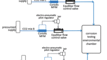
By locating a precision back pressure regulator downstream of the MFC, as shown in the schematic above, these spurious flow disruptions are avoided because the differential pressure across the internal control valve is kept constant.
Engineering Assistance with Your Flow Control Challenge
Most of the issues discussed above can be addressed by any back pressure regulator; however, the Equilibar® back pressure regulator is popular for a variety of research applications because its unique design offers several design advantages:
- Flow rate and Flow Coefficient turn-down ratio holds 0.5% precision across a range of 100,000:1
- Pressure ranges up to 300 bar (5000 psig) and 600 bar (10,000 psig)
- Elegant construction suitable for highly aggressive chemicals and high temperatures
Contact one of our application engineers to discuss your unique flow control challenges.
One of our research series regulators could be a good fit for your use with your MFC.
LF Research Series Back Pressure Regulator
- Port Sizes:
- 1/16"
- 1/8"
- 1/4"
- Typical Pressure Ranges:
- 0 - 1 in WC
- 0 - 7 in WC
- 0 - 10 in WC
- 0 - 28 in WC
- 0 - 0.7 psi
- 0 - 1.4 psi
- 0 - 2 psi
- 0 - 3 psi
- 0 - 5 psi
- 0 - 10 psi
- 0 - 20 psi
- 0 - 30 psi
- 0 - 60 psi
- 0 - 100 psi
- 0 - 150 psi
- 0 - 175 psi
- 0 - 200 psi
- 0 - 250 psi
- 0 - 300 psi
- 0 - 400 psi
- 0 - 500 psi
- 0 - 750 psi
- 0 - 1000 psi
- Key Applications:
- Catalysis Research Reactors
- Pilot Scale Reactors
- Mixed Phase Media
- Corrosive Media and Aggressive Chemistry